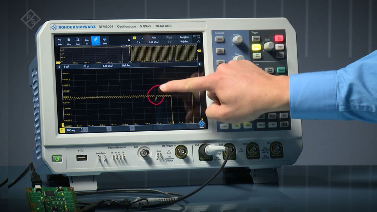
Zoom is a display tool that expands the view of the selected waveform. For more in-depth visual analysis or processing, the source trace can be expanded horizontally or vertically. Each zoom trace can have its own horizontal and vertical scale setting, enabling views of the source trace using multiple horizontal and vertical scales. Zooming is available on all digital oscilloscopes. Zoom is important because oscilloscopes can acquire gigasamples of data per acquisition, with a vertical resolution of 12 or more bits. A screen with a resolution of approximately 1920 x 1080 pixels is required to display this data. To fit on the screen, the data must be compressed if a full acquisition is displayed. A view of all the data that was acquired is possible by expanding the data using a zoom trace so that it fits within the resolution of the screen.
Zoom demo
Zoom can be invoked from this oscilloscope’s front panel using the Zoom button. It can also be evoked interactively by touching the touchscreen and dragging the resulting box over the area to be expanded. The Zoom Trace dialog boxes can also be used to control zoom traces (see Figure 1).
From Arthur Pini 0 Comments Print Friendly, PDF & Email
Zoom is a display tool that expands the view of the selected waveform. For more in-depth visual analysis or processing, the source trace can be expanded horizontally or vertically. Each zoom trace can have its own horizontal and vertical scale setting, enabling views of the source trace using multiple horizontal and vertical scales. Zooming is available on all digital oscilloscopes. Zoom is important because oscilloscopes can acquire gigasamples of data per acquisition, with a vertical resolution of 12 or more bits. A screen with a resolution of approximately 1920 x 1080 pixels is required to display this data. If a full acquisition is displayed, the data has to be compacted to fit on the screen. A view of all the data that was acquired is possible by expanding the data using a zoom trace so that it fits within the resolution of the screen. Zoom example The Zoom button on the front panel of this oscilloscope can be used to activate zoom. It can also be evoked interactively by touching the touchscreen and dragging the resulting box over the area to be expanded. The Zoom Trace dialog boxes can also be used to control zoom traces (see Figure 1).
Partner Content
EE Times’ Nitin Dahad Talks Edge AI with Infineon’s Thomas Rosteck
EE Times’ Nitin Dahad Talks Edge AI with Infineon’s Thomas Rosteck
10.24.2025
Maher Matta and Andreas Urschitz of Infineon join EE Times for a discussion of OktoberTech. Maher Matta and Andreas Urschitz of Infineon join EE Times for a discussion of OktoberTech. 10.24.2025
EDN talks to Infineon about the evolution of AI data centers. EDN Talks to Infineon About the AI Data Center Evolution
10.24.2025
Figure 1 An example of several zoom instances used to analyze a remote keyless entry system waveform. Each zoom trace can be controlled through the Zoom dialog box. Art Pini is the source In the top grid, trace M1 represents a remote keyless entry (RKE) system’s source waveform. The waveform comprises an amplitude-modulated RF carrier. The modulation encodes the commands to lock a car door. The fifth pulse in the acquired waveform is horizontally expanded using zoom. Note that the zoomed area is highlighted by increased intensity on the source trace. The expanded version appears in trace Z1 (second down from the top). The Z1 trace is controlled using the Z1 zoom dialog box at the bottom of the display.
The trace’s horizontal and vertical scale and offset can be adjusted interactively while observing the effects on the screen. The zoom trace’s vertical and horizontal scaling can be seen in the trace annotation box for the Z1 trace. Trace Z1 has a horizontal scale of 150 microseconds per division, compared to the 5 milliseconds per division scale of the M1 source trace, representing an expansion of thirty-three times.
The zoom trace reveals variations in the RF carrier amplitude at the start and end of the burst. These keying transitions affect the generation of spurious signals that can interfere with other RF services. The zoom trace Z2 expands the view of the trailing edge of the first zoom trace and displays it in detail in the third grid from the top. Here, we have an example of Zoom on Zoom.
After demodulating the signal in Z2, the analysis moves on to low-pass filtering the absolute waveform value. The demodulated signal can be measured to obtain the signal amplitude’s slew rate and the decaying amplitude’s time constant. On Zoom, this is an illustration of a math operation. The math trace F1 performs demodulation; the result is displayed in the bottom grid. This example used two zooms, each with a different horizontal scale.
Factors at the horizontal and vertical scales Zoom, in the oscilloscope used for this article, can be applied to any waveform, acquired signals, math, memory, or even other zoom traces. Zoom traces are waveforms like any other. They can be expanded further using another zoom trace, allowing the same signal to be viewed with multiple horizontal or vertical scale factors.
The application of math operators makes it possible to carry out arithmetic, filtering, or FFTs on them. In this family of oscilloscopes, all non-acquisition traces, such as memory or math traces, have zoom functionality. However, the number of available zoom traces typically matches the number of available acquisition traces. An ultrasonic range finder zooms in vertically on a double echo to reveal details of the waveform that can’t be seen in the acquired waveform. The vertical resolution of this waveform is twelve bits or 4096 levels. On a display with a vertical resolution of 1080 pixels, the full resolution must be rendered with at least a four-to-one vertical zoom. A comprehensive look at the structure of the waveform is provided by the echo at 5 mV per division in a ten-to-one vertical expansion.
Multi-Zoom
For the purpose of comparison, some applications employ multiple zoom traces with the same expansion factor. Consider the measurement of an I2C data signal and clock signals shown in Figure 3.
An I2C data signal is the signal in the top grid. The grid immediately below that is the associated I2C clock. These waveforms are expanded synchronously using a feature called multi-zoom. Multi-zoom locks the selected zoom traces together. This feature allows common horizontal control of all zoom traces. They can be expanded or contracted at the same time, locked in time, or offset by a time offset that is set by the user. In the example, the zoom traces Z1 and Z2 are the expansions of the data and clock signal, respectively. They are locked in time with no offset. The expanded view makes it easier to see the relative timing of the signals. So, the start condition, where the data signal is forced to a low state, followed by the clock signal being forced low, is easy to discern. The zoom traces incorporate the address field of the I2C packet. The expanded view afforded by the zoom displays is useful in evaluating physical layer issues like signal levels, period, with, transition times, and timing.
Automatic scrolling is very helpful when moving narrow zoom windows through very long acquisitions that might require an extreme number of turns of a knob. It offers two scan rates and the ability to jump to the extreme values.
Comparing waveform segments
Zoom displays can help compare waveforms. For instance, an acquired I2C data signal contains multiple data packets; Zoom can be used to display these packets on the same expanded timescale for comparison (Figure 5).
Packets 1, 2, and 4 from the acquired I2C data bus acquisition are separated and compared using three zoom traces with the same scale factors but with different offsets. The three packets’ data content differs in the last half millisecond of the waveforms, making the difference in length of packet 2 clear.
Using Zoom to window signals
An acquired signal can be selected or windowed by Zoom for further processing. This allows the examination of selected parts of a signal separately. Consider conducting an investigation into an RKE system that encodes commands using frequency shift keying (FSK) (Figure 6).